In precision grinding, workpiece surface quality is a crucial indicator for evaluating process stability and equipment accuracy. Among surface defects, short wave marks are a common but often subtle anomaly. While not obvious scratches, they can affect part fit, optical reflection properties, or subsequent coating quality.
The appearance of short wave marks often stems from minor vibrations or rotational inconsistencies during machining, involving factors such as belt drives, spindle seals, hydraulic systems, gears, and motors.
To effectively improve grinding stability and product quality, this article will systematically explain various possible causes, serving as a reference for equipment inspection and process management.
Table of Contents
What Are Short Wave Marks in Grinding?
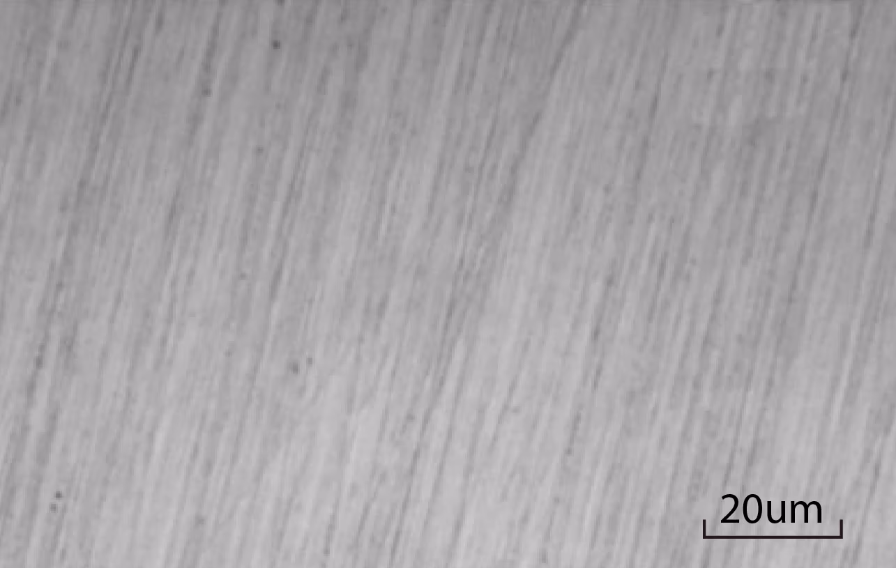
Grinding short wave marks refer to regular or irregular patterns with very small spacing and short wavelengths that appear on the workpiece surface. These patterns are usually very subtle, typically ranging from tens of micrometers to several millimeters, and may require careful observation to detect, but they affect the workpiece’s surface roughness and accuracy.
Main Characteristics of Grinding Short Wave Marks
- Short Wavelength: Compared to long wave marks, the distance between peaks and troughs of short wave marks is very small.
- Regular or Irregular Spacing: The pattern arrangement may have a certain regularity or exhibit an irregular distribution.
- Subtle: Usually very small in size, possibly requiring a magnifying glass or surface roughness measuring instrument for clear identification.
- Affects Surface Quality: Even if not easily discernible by the naked eye, short wave marks increase surface roughness (Ra, Rz values, etc.), affecting subsequent processing or use.
Causes and Solutions for Short Wave Marks
Cause One: Vibration from the Belt
When the belt thickness is uneven, during belt transmission, the center distance between the driving pulley and the driven pulley will fluctuate slightly with changes in belt thickness. This fluctuation can cause the spindle to experience slight speed fluctuations or axial runout during rotation, forming periodic mechanical vibrations.
Since grinding is a high-precision process, these subtle vibrations will directly reflect onto the workpiece surface, causing short wave marks.
Solutions for Belt Vibration
- Check if the belt thickness is uniform. If not, replace it with a higher-quality belt.
- Adjust belt tension to the appropriate range, avoiding it being too loose or too tight.
- If using a V-belt, you should:
- Check if the belt cross-section matches the groove wheel;
- If necessary, select a V-belt with a smaller cross-section to reduce interference with the groove.
- Confirm that the groove wheels are coaxially aligned and parallel, and also confirm that the groove angle is appropriate to avoid skew.
- Regularly check the wear status of the belt and groove wheel, and replace them if necessary.
Cause Two: Vibration from Other Machinery
Even if the grinder’s own mechanism is in good condition, vibrations generated by surrounding equipment during operation can still be transmitted to the grinder, potentially causing micro-vibrations between the workpiece and the grinding wheel, leading to intermittent contact and inducing short wave marks.
(Micro-vibration → Causes intermittent contact → Induces short wave marks)
In grinders with a large swing diameter, when the workpiece and grinding wheel are suspended high above the support surface, they are very susceptible to external vibrations if there is no special foundation.
How to Determine if Vibration Comes from the Machine Body
After stopping the grinder’s operation, you can check for vibration sources from the machine body or environment in the following ways:
- Install an indicator at a fixed part of the machine body and observe if its needle shows abnormal shaking.
- Place a cup of water on the grinding wheel spindle housing and observe if the water surface shows continuous fluctuations. If abnormal vibration occurs when not operating, it can be concluded that the vibration is caused by the external environment of the machine.
Recommended Condition Adjustments for Grinding Rolls with Fine Grit, Soft Bond Grinding Wheels
When grinding rolls with fine-grit, soft-bond grinding wheels, if short wave marks or machining instability occur, consider the following countermeasures:
- Reduce the grinding wheel’s rotational speed to 60% to 70% of the original setting.
- Lowering the wheel speed can reduce cutting force variations and thermal deformation during machining, thereby improving grinding stability and suppressing the generation of short wave marks.
Cause Three: Hydraulic System Vibration
During grinder operation, if the hydraulic pump or relief valve malfunctions, it can lead to unstable hydraulic system pressure, which in turn generates periodic or intermittent vibrations. These vibrations will transmit to the spindle or workbench, causing short wave marks to form on the workpiece surface.
How to Diagnose Hydraulic Faults
- If the relief valve needs to be adjusted to extremely low pressure for the system to operate stably, it indicates that the hydraulic unit may be faulty or severely worn.
- If the abnormal phenomena of each unit in the hydraulic system are already quite obvious, the faulty components should be inspected and replaced one by one to “treat the symptoms.”
Other Potentially Related Factors
In addition to the hydraulic unit itself, attention should also be paid to whether the following parts have abnormalities:
- Coupling alignment and concentricity: If eccentric or loose, it may also generate vibration.
- Cooling pump operation: Cooling pump abnormalities can cause fluid pressure fluctuations, further affecting system stability.
Cause Four: Vibration from the Motor
Comprehensive Inspection of All Motor Vibrations
- Use a vibration meter or tactile sensation for preliminary judgment, and conduct further inspection for abnormal vibrations.
If a motor exhibits vibration, check it according to the following steps:
- Is it securely fastened to the base: If the motor is not securely fixed, it will generate resonance and runout during operation.
- Are the pulleys balanced: Unbalanced pulleys will cause eccentric operation, leading to associated vibrations. A dynamic balancing machine can be used for inspection and adjustment.
- Is the motor shaft misaligned or eccentric: Check if the shaft is bent or misaligned with connecting shafts, such as couplings. Perform shaft alignment if necessary.
Cause Five: Vibration from Chains and Sprockets
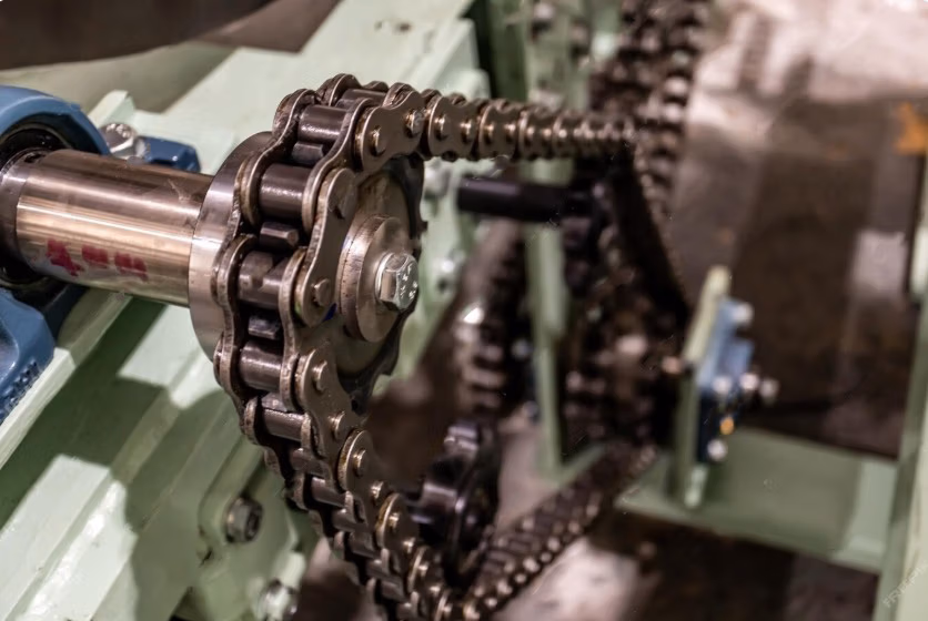
In grinding equipment, if the workpiece drive mechanism uses chains and sprockets for transmission, special attention must be paid to the following points to avoid the appearance of short periodic waviness on the workpiece surface due to unstable transmission:
- Polygonal Effect
- The actual motion of the sprocket is not perfectly circular but exhibits a polygonal motion path, known as the “polygonal effect.” This leads to periodic fluctuations in the instantaneous speed of the chain’s output motion.
- The larger the drive sprocket (more teeth), the smaller this ripple effect, which helps improve rotational smoothness.
- If a drive sprocket with too few teeth is used, or the chain angle changes too much, it can easily cause microscopic periodic changes in workpiece rotation, leading to short wave marks during grinding.
- Chain Tension Adjustment:
- Maintaining proper chain tension helps stabilize transmission and reduces uneven machining caused by chain slackness or jumping.
- Too loose tension will lead to skipped teeth and impact, while too tight tension will increase load and cause vibration.
Part Wear Inspection and Replacement:
- If the vibration comes from severe wear of the chain or sprocket (e.g., elongation, tooth profile deformation, runout, etc.), new parts should be replaced immediately to restore transmission stability.
- Regular lubrication and tension checks can extend lifespan and reduce instability factors.
Cause Six: Spindle Headstock Seal Too Tight
In grinding equipment, if the spindle headstock uses felt or other sealing materials as a dust-proof or oil-proof structure, attention should be paid to whether the sealing pressure is excessive.
Impact of Overly Tight Seal Material:
- When the seal is too tight, it creates resistance on the spindle, acting like a “brake.”
- This resistance interferes with the normal rotation of the spindle, and abnormal motion may occur even if the belt tension is correct or slightly loose.
※Note: When the belt is loose, the panel should be easily rotated by hand; this is the normal state.
Symptoms of Overly Tight Seal Material
If the seal is too tight, even if the belt is loose, it will cause intermittent obstruction to spindle rotation:
- When the belt is too tight: Spindle movement is jerky.
- When the belt is loose: Spindle speed may decrease or even stop.
- This phenomenon will repeat several times per revolution, causing irregular or periodic rotational interference.
How to Solve the Problem of Overly Tight Seal Material:
- Check the spindle seal pressure to ensure proper contact of the sealing material without excessive friction.
- If using felt seals, consider their compression amount and lubrication status.
- During testing, loosen the belt and manually rotate the spindle to confirm that rotation is smooth and free of abnormal resistance.
- If necessary, replace with low-friction coefficient sealing materials or adjust the installation method to reduce compression.
Cause Seven: Incomplete Gear Action
In grinders where workpiece rotation is driven by gear transmission, if the gears operate incompletely or unstably, it will directly affect the uniformity of workpiece rotation contact, leading to short wave marks.
Common Abnormal Phenomena:
- Incomplete gear meshing or discontinuous action will cause small but continuous variations in workpiece rotational speed.
- These variations will cause the grinding wheel to contact for longer periods at certain points and quickly pass over others, resulting in inconsistent surface machining.
Countermeasures for New and Worn Gears
Improper meshing of new gears in the initial stage:
- If the problem occurs with newly replaced gears, it may be due to poor meshing caused by microscopic interference on the surface or machining marks.
- Manual lapping can be performed using lubricating oil mixed with a small amount of soft abrasive to promote tooth surface conformity.
※ Note: The lapping process requires careful control to avoid abrasive being too coarse or applying excessive force, which could cause tooth profile distortion or damage to gear accuracy.
Worn or damaged gears:
- When gears show obvious wear, pitting, missing teeth, or eccentricity, it will exacerbate transmission instability.
- In this case, the gears should be replaced to avoid further impact on machining quality.
Conclusion
Short wave marks are common surface defects in grinding, typically formed due to mechanical vibration or unstable transmission systems. From uneven belt thickness, motor or chain vibration, overly tight spindle seals, to poor gear transmission, all can cause periodic changes in workpiece rotation, leading to uneven contact between the grinding wheel and the workpiece surface, thus forming short wave marks. Therefore, to prevent and improve short wave marks, it is necessary to start from the overall transmission system and vibration sources, troubleshoot and calibrate them one by one, ensuring smooth transmission, sufficient structural rigidity, and the use of appropriate grinding wheel conditions and machining parameters. Through systematic inspection and maintenance, workpiece surface quality can be effectively improved, avoiding rework and increased defect rates.
Action
- How to choose grinding wheel>>>How to Choose Between Diamond Wheels and CBN Wheels?
- Correctly understand the situation of grinding abnormality>>Causes of Grinding Abnormalities? How to Address Them?
- How to choose tools for cutting bonded grinding wheels>>How to Dress Grinding Wheels with Different Bond Type
- Is the current grinding wheel wear normally>>>What is the current status of the grinding wheel? – Electroplated Grinding Wheel Section
- How to dress a grinding wheel>>Grinding Wheel Dressing and Sharpening Methods
- Grinding wheel dressing in two stages>>What Are Truing and Dressing of Grinding Wheels?
- How to choose tools for cutting bonded grinding wheels>>How to Choose Grinding Wheel Dressing Tools
- Different grinding states of cutting edge>>In-depth understanding of grinding wheel cutting edge shapes, variations, and self-sharpening mechanisms
- What is the difference in the grinding of bonded grinding wheels?>>How to Dress Grinding Wheels with Different Bond Type
- What should I do if scratches and burns appear on the grinding surface?>>Scratches and Burns on the Ground Surface? Causes and Improvement Methods!
- What to do if chatter lines appear>>What to Do When Chatter Marks Appear in External Cylindrical Grinding? A Comprehensive Analysis of Causes and Solutions
- Grinding anomalies such as wheel packing, smoothing and workpiece cracking>>Avoiding Grinding Wheel Clogging, Glazing, and Workpiece Cracking: Understanding Common Pitfalls and Improvement Solutions in Grinding
- What is bonding?>>What is Bonding Degree and How Do I Choose?
- Implement>>Diamond and boron nitride grinding wheels, polishing abrasives, polishing equipment, polishing tools, diamond dressing tools
- How to dress different bonding agents>>How to Dress Grinding Wheels with Different Bond Types
- Review
We offer customized adjustments to the grinding process, tailored to meet processing requirements for maximum efficiency.
After reading the content, if you still don’t know how to select the most suitable option,
Feel free to contact us and we will have specialist available to answer your questions.
If you need customized quotations, you’re also welcome to contact us.
Customer Service Hours: Monday to Friday 09:00~18:00 (GMT+8)
Phone: +8867 223 1058
If you have a subject that you want to know or a phone call that is not clear, you are welcome to send a private message to Facebook~~
Honway Facebook: https://www.facebook.com/honwaygroup
You may be interested in…
[wpb-random-posts]