
Processing can generally be divided into two major categories: one involves mass replication after mold creation, and the other uses various tools and specific materials to craft the required shape. Individual processing is further divided into the following three main categories:
1. Cutting: Includes drilling, milling, and turning.
2. Grinding: Includes surface grinding and cylindrical grinding.
3. Electrical Discharge: Includes electrical discharge machining and wire-cutting.
This article focuses on precision cutting, primarily through the use of precision cutting tools.
Applications of Precision Cutting
Precision cutting is typically used for workpieces requiring high accuracy, reliability, strength, shape flexibility, and small-batch production:
(1)Parts supporting high-speed motion: e.g., aircraft engines.
(2)Components in manufacturing tools and devices: e.g., semiconductor equipment.
(3)Parts in low-volume production devices and machines: e.g., aerospace-related parts.
The operation of precision cutting tools depends on their shape, material, motion, and strength.
Variations in tool shape affect their lifespan and rigidity.
Front rake angle
Larger angles result in better tool conditions and less heat generation but lower rigidity, making the tool more prone to chipping. 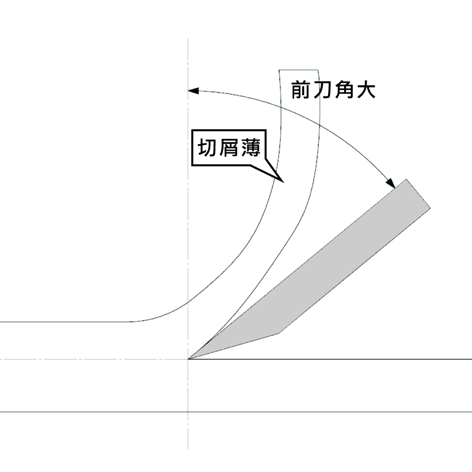
Smaller angles result in worse tool conditions, with more heat generation but better resistance to chipping.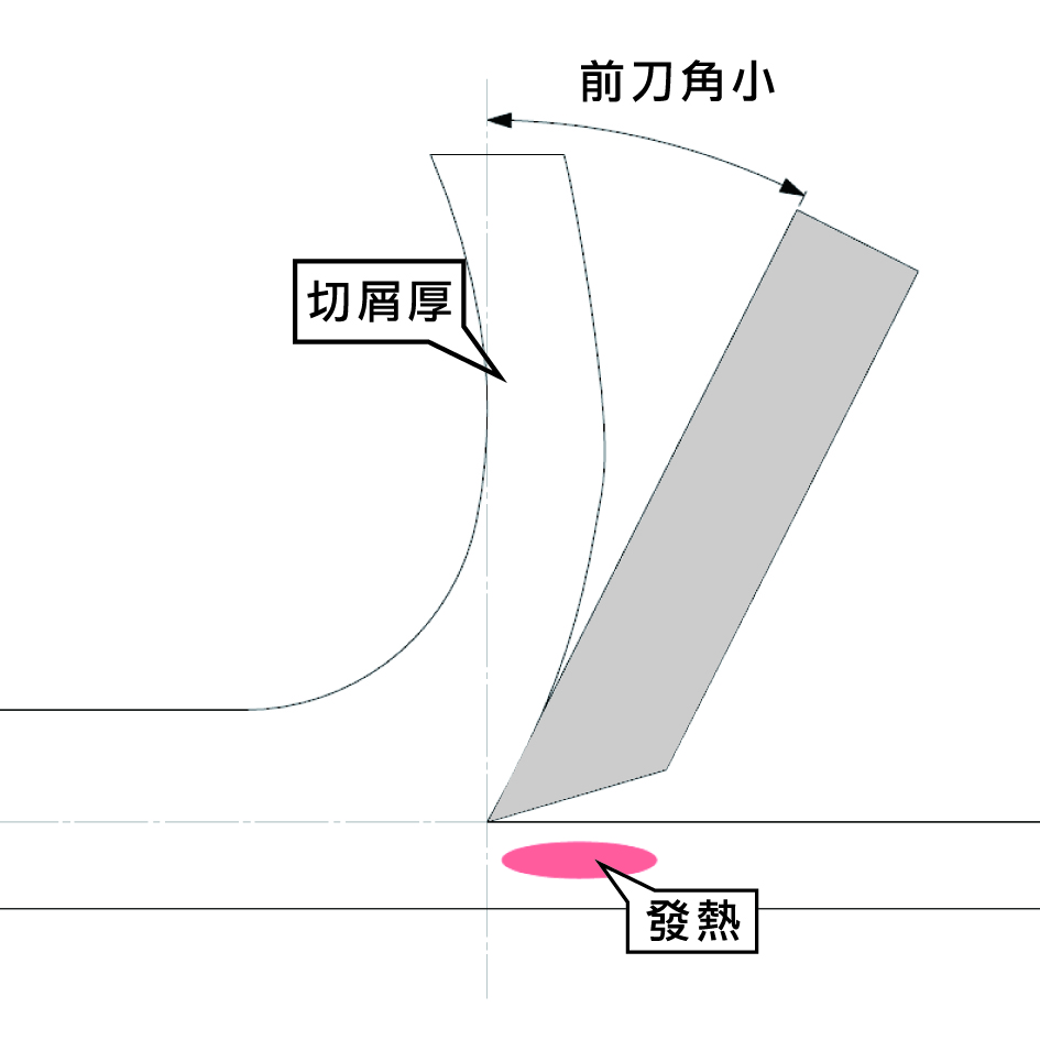
Back rake angle
Larger angles lead to less wear on the back surface, allowing for longer tool life, especially suitable for cutting adhesive materials like aluminum.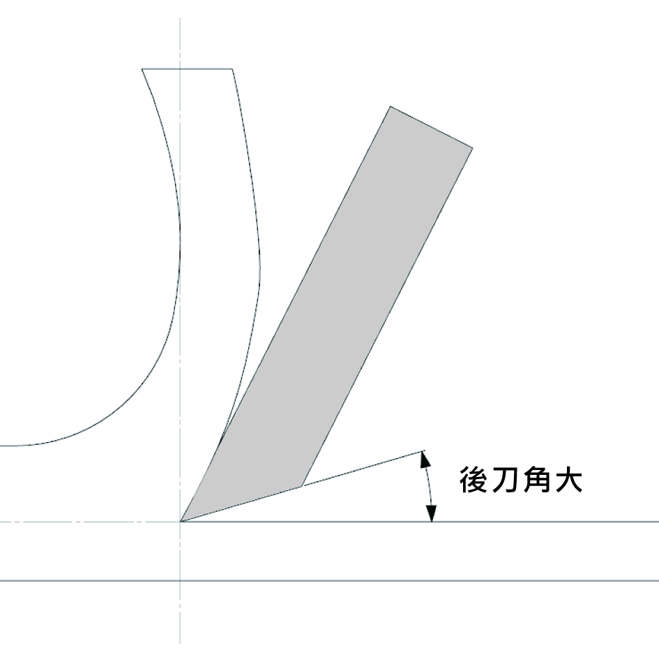
Smaller angles increase wear on the back surface and accelerate tool wear due to heat generation.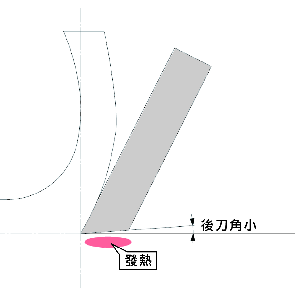
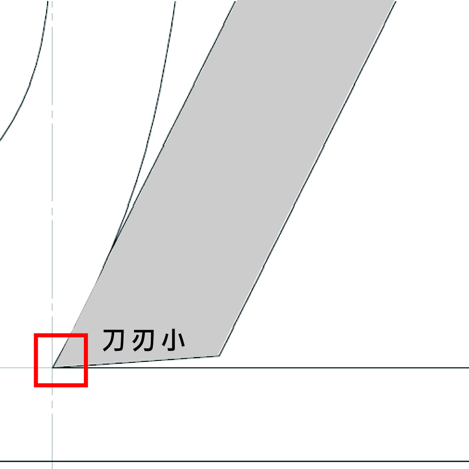
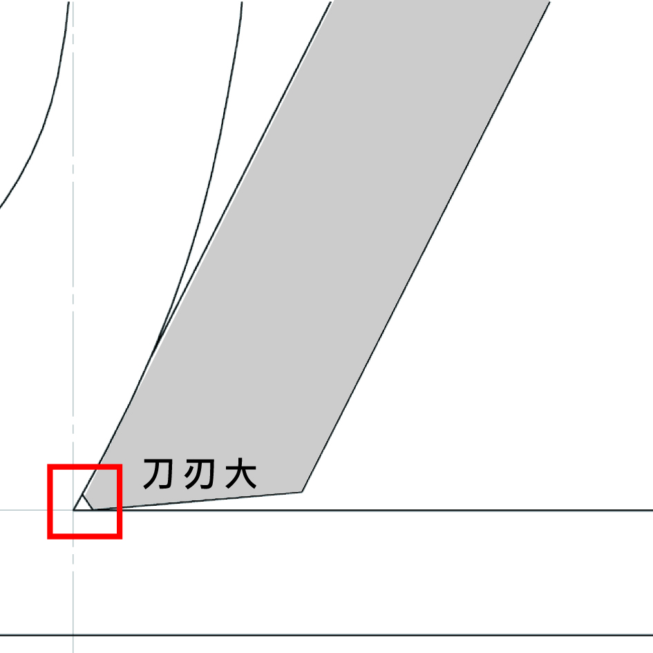
Sharpness of the cutting edge
In general, the tip of a cutting tool has a small R (radius) or C (chamfer) edge, referred to as cutting edge.
Smaller cutting edges provide better tool condition but are more prone to chipping.
Larger cutting edges provide worse tool condition but are more resistant to chipping.
Chip breaker grooves
Different manufacturers offer various patterns to rapidly curl and break chips produced during cutting.
Number of flutes on end mills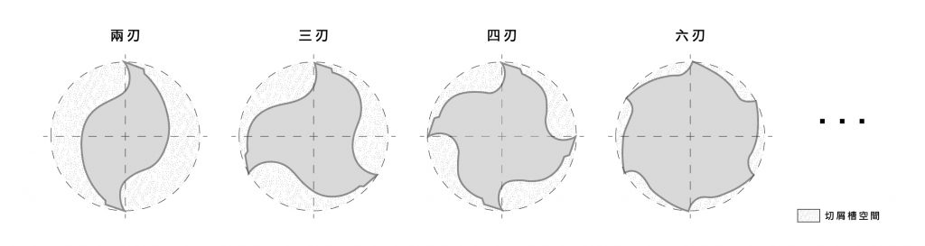
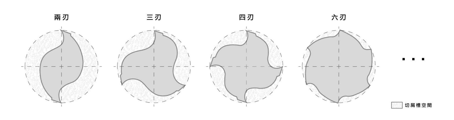
More flutes provide better rigidity but are prone to clogging, making them unsuitable for groove machining.
Fewer flutes offer more space for chip removal.
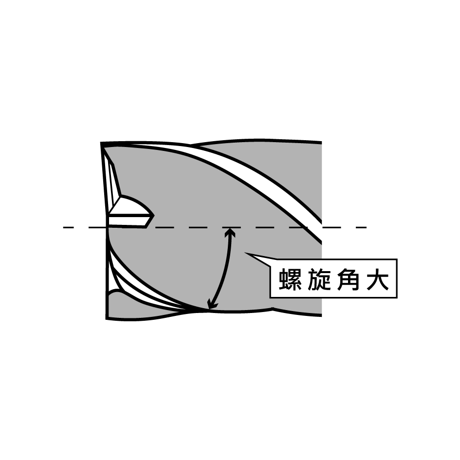
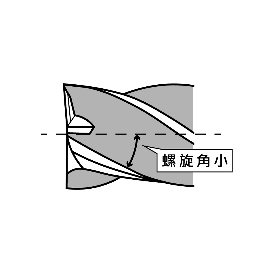
Helix angle on end mills
Larger helix angles offer weaker rigidity, suitable for side finishing.
Smaller helix angles provide better rigidity, suitable for deep groove machining.
Common Tool Materials
1.Diamond sintered bodies
2.Cubic boron nitride (cBN) sintered bodies
3.Ceramics
4.Cermet (metal-ceramic composites)
5.Carbide
6.High-speed steel (HSS)
The selection of tool materials is based on hardness, toughness, heat resistance, and adhesion resistance, as well as compatibility with the material being cut (e.g., diamond is hard but unsuitable for cutting carbon steel due to a chemical reaction with carbon that shortens its lifespan).
Tool Operation
Cutting speed refers to the speed at which the tool acts on the material, usually expressed in meters per minute (m/min). For rotating tools, cutting speed refers to the circumferential speed of the tool’s outer diameter as it rotates, often called the peripheral speed.
Cutting can be classified into continuous and interrupted cutting:
Continuous cutting minimizes impact force but generates heat over time.
Interrupted cutting involves repeated tool engagement, generating higher impact forces but producing less heat compared to continuous cutting.
Tool Strength
Insufficient tool rigidity can lead to chatter during machining, accelerating tool wear and making it difficult to meet precision requirements.
The rigidity of the tool holder, machine itself, and workpiece is also crucial. If the workpiece lacks sufficient rigidity, clamping methods can help reduce the impact. For structures that cannot be clamped, using sharper tools to reduce cutting load and minimize workpiece deformation is necessary.